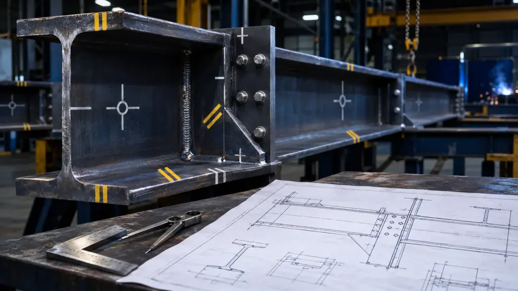
Steel assembly marking connects a fabricated assembly to the drawings, parts and schedules used to make and place it. An assembly mark identifies the assembled item; a piece mark identifies an individual component. Keeping those references consistent lets a workshop move from a drawing to a cut part, a welded assembly and an erection location without guessing.
This guide covers the identification workflow within a steel drawing package. For the wider detailing scope, see our structural steel shop drawings.
Piece marks and assembly marks answer different questions
A piece mark answers, “Which component is this?” An assembly mark answers, “Which fabricated unit does this drawing describe?” A beam assembly may contain a main member, end plates, stiffeners and cleats. Those components need a clear relationship to the assembly that contains them.
The drawing number is another identifier. It locates the document, while the assembly mark locates the item represented by it. Some office systems deliberately connect the two, but that relationship should be defined in the project convention rather than assumed.
Tekla Structures, for example, provides separate settings for part and assembly position numbers. Its numbering documentation illustrates why these identifiers need to be managed as distinct records. Agree the project’s mark format before creating drawings or reports.
An illustrative assembly
Imagine an assembly identified as A101. Its assembly drawing shows a main member, two end plates and four stiffeners. In a project-specific example, the main member could be P201, the end plate P202 and the stiffener P203. The component list would record the required quantity of each piece for one A101 assembly.
| Example reference | What it identifies | Check |
|---|---|---|
| A101 | The fabricated assembly | Matches the assembly drawing and erection reference. |
| P201 | Main member | Matches the component detail and assembly list. |
| P202 | End plate | Quantity and handedness agree with the assembly view. |
| P203 | Stiffener | Locations and quantity agree with the assembly details. |
These are invented identifiers, not a required Australian numbering format. Use the fabricator’s agreed system, including any project, phase or sequence prefixes.
Check quantities at the correct level
Distinguish the quantity of a component in one assembly from its total quantity across the project. If three assemblies each require two end plates, a per-assembly list showing two plates and a project report showing six can both be correct. A missing quantity basis makes them look contradictory.
Check the report heading, assembly count and any loose parts before reconciling totals. Bolts or components delivered loose may be handled separately from shop-fitted items. Their references still need to lead to a clear instruction about where they belong.
Control marks when the design changes
A change to a hole pattern, connection or member orientation can affect identification as well as geometry. Follow the project’s numbering rules and review the effect on drawings, lists and previously issued information. Do not silently reuse an identifier for a changed item without checking how recipients will distinguish it from earlier work.
Keep a change record that states the affected mark, drawing revision, reason for change and the action required from recipients. Where material is already cut or an assembly is fabricated, flag that condition for the responsible project team before reissuing the documentation.
A release checklist for the drawing package
- Confirm mark prefixes and numbering conventions with the fabricator.
- Check assembly marks against general arrangements and erection references.
- Match piece marks between component drawings and assembly lists.
- Reconcile quantities using the same assembly and project scope.
- Check mirrored or handed items against the actual geometry.
- Review changed marks and communicate the effect on previous issues.
- Compare issued PDFs, native files and exported lists for revision consistency.
Digital identification and the physical marking method are separate decisions. Agree how the workshop and site will identify items, including any restrictions associated with finishes or exposed work, through the fabricator’s project procedures.
Preparing steel documentation for fabrication
Draftings Australia provides fabrication-ready detailing for steel fabricators, builders and engineering contractors across Australia. Our existing steel detailing scope includes member marks, cutting lists and schedules.
Send the engineer’s drawings, fabrication conventions and intended issue sequence when requesting fabrication drawings. If marks have already been issued, include the current register and reports so the next package can be checked against them. Contact Draftings Australia to discuss the drawing scope.