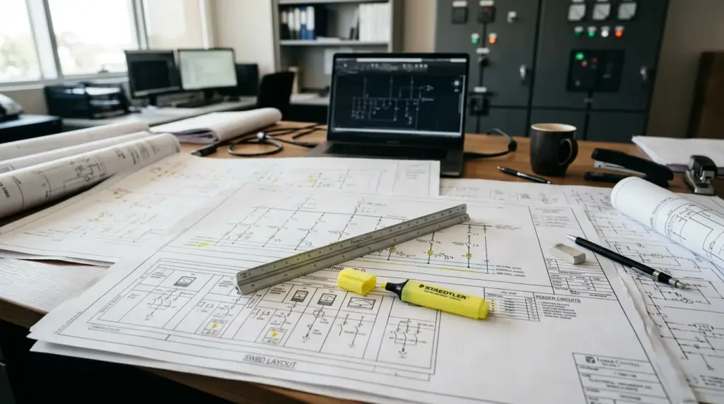
“Electrical drawings” covers a family of documents, not one. A switchboard builder, an installer on a commercial fit-out and a certifier reviewing a mining substation each need a different drawing, and a set that uses the wrong one for the job is the usual reason an electrical package comes back with questions. This guide sets out the main types of electrical drawing, what each one is for, and how they fit together in a working set.
Single-line diagrams
The single-line diagram (SLD), also called a one-line diagram, is the top of the hierarchy. It shows the power distribution system from the supply point down through main switchboards, distribution boards and major loads, with each three-phase circuit drawn as a single line. It carries protective device ratings, cable sizes, transformer ratings, metering points and fault levels.
An SLD is the drawing an engineer reads to understand how the installation is supplied and protected. It deliberately leaves out physical location. If it is wrong, every drawing beneath it inherits the error, so it is normally the first drawing issued and the last one closed out at as-built stage.
Schematic and wiring diagrams
A schematic diagram shows how a circuit works rather than where it sits: contacts, coils, relays, interlocks and control logic laid out so that the sequence of operation can be followed. Control schematics for motor starters, pump controls and switchboard interlocking are the common examples.
A wiring diagram goes one step further and shows each physical conductor between terminals, with terminal numbers and wire numbers, so that a panel can be wired and later fault-found. The two are often confused. A schematic answers “how does this work?”; a wiring diagram answers “which wire goes to which terminal?”. Our page on schematic drawings covers the drafting side of schematics in more depth.
Layout drawings: lighting, power and communications
Layout drawings are the plan-view sheets an installer works from. They place every light fitting, switch, general power outlet, data point and fixed appliance connection on the architectural background, with circuit references that tie each item back to its distribution board.
- Lighting layouts show fittings, switching and circuit grouping, and often emergency and exit lighting on a separate sheet or layer.
- Power layouts show outlets, isolators and dedicated circuits for fixed equipment.
- Communications and security layouts show data, CCTV, access control and fire detection devices where those services are in the electrical scope.
Layouts depend on an up-to-date architectural background. A layout drawn over a superseded floor plan is one of the most common sources of rework, because outlets end up on walls that have moved.
Switchboard general arrangement drawings
A switchboard GA shows the physical board: overall dimensions, door and escutcheon layout, the position of each device, labelling, cable entry points and mounting. It is what the switchboard manufacturer builds from and what the site team uses to check clearances in the switchroom. It is read alongside the SLD for that board, which defines what the devices are, and the schematic, which defines how they are controlled.
Cable schedules and cable route drawings
On anything larger than a small commercial job, cabling is documented in two places. The cable schedule is a table listing every cable by number, with its origin, destination, type, size, number of cores and length. Cable route or cable tray drawings show where cable ladder, tray and conduit run through the building or plant, including levels and support points.
Cable selection itself is an engineering task governed by Australian standards for current-carrying capacity and voltage drop. The drawings record the result; they do not replace the calculation.
Earthing and lightning protection drawings
Earthing drawings show the main earthing terminal, earth electrodes, equipotential bonding of exposed metalwork and, on industrial sites, the earth grid. On mining, oil and gas and other hazardous-area sites they are often among the most scrutinised drawings in the set, because they are the evidence that the installation will clear a fault safely.
Block diagrams and riser diagrams
Block diagrams show a system at a high level, such as a building management or fire system, as boxes and connections, with no electrical detail. Riser diagrams show how services travel vertically through a multi-storey building, floor by floor. Both are communication drawings: they let a reviewer understand the system before reading the detailed sheets.
Symbols, standards and conventions
Electrical drawings rely on graphical symbols far more than other disciplines, so consistency matters. Every set should carry a legend sheet that defines every symbol used, even standard ones, because symbol libraries differ between firms and between versions of the same CAD platform. Australian electrical installations are designed to the wiring rules, AS/NZS 3000, and general drawing practice follows the conventions in the AS 1100 series; our guide to AS 1100 drawing conventions covers line types, lettering and title blocks. Standards themselves are published by Standards Australia.
Workplace electrical safety obligations, including those that drawings support such as isolation and labelling, are set out by Safe Work Australia and the state regulators.
Problems that show up in electrical sets
- Circuit references that do not match. A layout calls a circuit DB-2/14 that the board schedule lists as spare, or the reverse. This is the single most common query from installers.
- SLDs that stop at design stage. Protective device ratings change during construction and the SLD is never updated, so the as-built record no longer describes the installation.
- Backgrounds out of date. Layouts drawn over a superseded architectural plan put outlets on walls that have moved or in rooms that have been re-planned.
- Symbols without a legend. Library symbols from different projects mixed in one set, with no legend sheet to say which is which.
- Cable schedules that do not reconcile. Cables on the route drawings that are missing from the schedule, or schedule entries with no route, which makes quantity take-off and installation checking unreliable.
- Revision changes with no clouds. A board GA re-issued at revision C with nothing to show which devices moved.
Almost all of these are coordination problems rather than drafting skill problems. A short cross-check before each issue, walking every circuit from layout to board to SLD, catches most of them while they are still cheap to fix.
How the drawings fit together
A well-organised electrical set reads from system to detail: legend, single-line diagrams, schedules, then layouts, then switchboard GAs, schematics and wiring diagrams, then earthing and details. Every circuit on a layout should trace to a board on the SLD, every board on the SLD should have a GA, and every cable on a layout should appear in the schedule. Checking those cross-references before issue removes most of the queries an installer would otherwise raise.
Electrical drawings also rarely stand alone. They are coordinated with mechanical and hydraulic services, which is covered in our guide to MEP drawings, and they are exchanged between consultants in formats discussed in our article on CAD file formats.
For an overview of what an electrical drafting service covers, see our electrical drafting services article, or get in touch to discuss a set.