What are the basics of solid modelling?
Each solid modeling software offers unique methods for creating and working with solid models. Simple solid modelling programs allow you to build models using solid primitives, which are objects such as boxes, cones, spheres, and cylinders that you combine, subtract, and edit to produce a final model. The process of adding and subtracting primitive shapes is known as a Boolean operation in geometry (see Figure). Boolean operations also apply to more complex solid models defined by features and surfaces.
In contrast to modelling with solid primitives, feature-based solid modelling programs allow you to construct solid models using more intuitive feature tools. A feature often begins with a 2-D sketch, followed by a sketched feature such as extrusion or revolution created from the sketch. Additional features include adding or subtracting solid material to generate a final model. Many feature-based solid modelling programs are highly sophisticated and include many advanced tools and functions that significantly automate the design and documentation process. Parametric solid models are the most common models created using feature-based solid modelling software. Parametric refers to the method of using parameters and constraints to drive object size and location to produce designs with features that adapt to changes made to other features. Some solid modelling programs generate nonparametric solids, known as basic solids or dumb solids.

Parametric Solid Modeling

Parametric design tools allow you to assign parameters or constraints to objects. Parameters are geometric characteristics and dimensions that control model geometry’s size, shape, and position. A database stores and allows you to manage all parameters. Parametric design is also possible with some 2-D CADD programs. The parametric concept, also known as intelligence, provides a way to associate objects and limit design changes. You cannot change a constraint so that it conflicts with other parametric geometry. Parameters aid the design and revision process, place limits on geometry to preserve design intent, maintain relationships between objects, and help form geometric constructions.

Model Work Environments


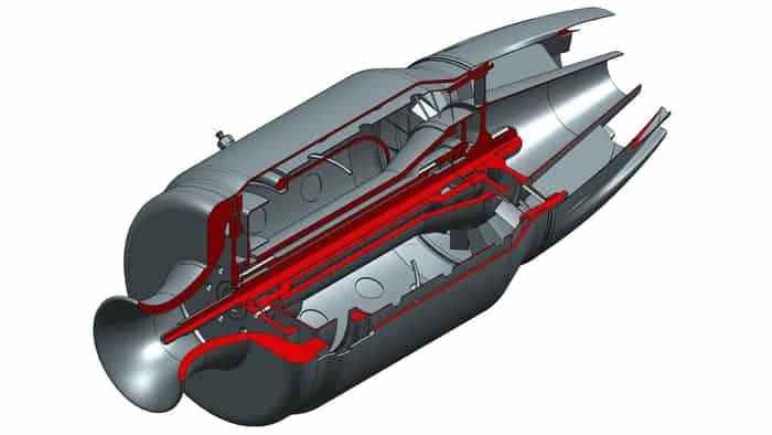
Parametric solid modelling software often includes several work environments and unique file types for different applications. A part file allows you to create a part model, such as the engine block shown in Figure. A part is an item, product, or element of an assembly. Some systems include separate files or work environments for specialised part modelling and related applications, such as sheet metal part design, surface modelling, analysis and simulation, and rendering.
An assembly file allows you to reference component files to build an assembly model. Components are the parts and subassemblies used to create an assembly. A subassembly is an assembly that is added to another assembly. The figure shows an engine subassembly that references the engine block part shown in Figure.
Part Model Elements

Every part model usually contains at least one sketch and at least one sketched feature. A sketch is a 2-D or 3-D geometry that provides the profile or guide for developing sketched features (see Figure). A parametric sketch includes geometric constraints that define common geometric constructions such as two perpendicular lines, concentric circles, equal-sized objects, or a line tangent to a circle. Dimensional constraints specify the size and location of sketch objects. Examples of sketched features built from a sketch include extrusions, revolutions, sweeps, and lofts. Normally, the initial feature on which all other features are built, known as the base feature, is a sketched feature, such as the extrusion shown in Figure.
Adding placed features requires specifying size dimensions and characteristics and selecting a location, such as a point or an edge. No sketch is necessary. You typically use a dialogue box or other on-screen tool to describe size data. The figure shows two of the most commonly placed features: chamfers and fillets. Placed features are also known as built-in, added, or automated features. Shells, threads, and face drafts are other examples of placed features.
Assembly Modeling

Another option is to create new components within an assembly file or in place. This is an example of a process that some designers refer to as top-down design. Both assembly techniques are effective, and a combination of methods is common. However, for some applications, developing components in place is faster, easier, and more productive. Developing components in an assembly file usually creates an assembly and a separate part or assembly file for each component.

Editing Parametric Solid Models

Parametric geometry allows you to make any necessary changes to the design of a model, allowing you to assess design alternatives almost immediately by changing, adding, or deleting sketches, features, dimensions, and geometric controls. Parameter-driven assemblies allow changes made to individual parts to reproduce automatically as changes in the assembly and assembly drawing. Adaptive parts in assemblies are effective when you may not know the exact dimensions of a part or you may not fully understand the relationship between assembly components. Adaptive parts modify automatically if another part changes. Paramedic geometry also allows you to develop equations that drive your models, allowing a few dimensions to define the entire model or even create a family of related parts.
Extracting Drawing Content

Draftings Australia provides excellent 3d printing, 3d modelling services at an affordable rate. Call Us now!
How many types of solid modeling are there?
Solid modeling in CAD (Computer-Aided Design) refers to the creation and manipulation of three-dimensional solid objects and shapes. There are primarily two types of solid modeling techniques:
Parametric Solid Modeling: Parametric solid modeling involves creating solid objects using mathematical parameters and constraints to define their shape, size, and relationships. Parametric modeling allows designers to create flexible and easily modifiable solid models by associating geometric features with parameters and constraints. Changes made to one part of the model automatically propagate to related parts, maintaining design intent and consistency. Parametric solid modeling techniques include:
a. Feature-Based Modeling: Feature-based modeling involves creating solid models by adding or subtracting geometric features such as extrusions, revolves, sweeps, holes, fillets, and chamfers. Features are defined parametrically and can be easily modified or suppressed to adapt to design changes.
b. History-Based Modeling: History-based modeling captures the sequence of operations used to create a solid model, allowing designers to edit and modify the model by changing the order or parameters of operations. History-based modeling maintains a parametric relationship between the model and its construction steps, enabling efficient design iteration and exploration.
Direct Solid Modeling: Direct solid modeling involves creating solid objects by directly manipulating their geometry without relying on predefined parameters or constraints. Direct modeling allows designers to edit and modify solid models intuitively by directly manipulating faces, edges, and vertices. Direct solid modeling techniques include:
a. Push-Pull Modeling: Push-pull modeling allows designers to push or pull faces, edges, and vertices of a solid object to modify its shape and size. This intuitive approach enables quick and interactive editing of solid models without the need for complex parameterization.
b. Explicit Modeling: Explicit modeling involves creating solid models by defining geometric shapes and relationships directly, without associating them with parameters or constraints. Explicit modeling is often used for rapid concept modeling, freeform design, and artistic expression.
Both parametric and direct solid modeling techniques have their advantages and are suitable for different types of design tasks and workflows. Parametric solid modeling is preferred for designs that require precise control, design intent management, and design automation, while direct solid modeling is preferred for quick concept exploration, intuitive editing, and freeform design. Depending on the requirements of the design project and the preferences of the designer, CAD users may employ one or both types of solid modeling techniques to create and manipulate solid objects effectively.
What is a model of a solid?
AD (Computer-Aided Design) software. In CAD, a solid model represents an object as a closed, watertight volume bounded by surfaces, edges, and vertices. Solid models are used to represent physical objects, components, and assemblies in virtual space, allowing designers and engineers to visualise, analyse, and manipulate them digitally before manufacturing or construction.
Key characteristics of a solid model include:
Geometric Representation: Solid models accurately represent the geometry, shape, and size of physical objects using geometric primitives such as points, lines, curves, surfaces, and volumes. Solid models define the boundaries and interior features of objects, providing a detailed representation of their form and structure.
Topology and Connectivity: Solid models maintain the topology and connectivity of objects by defining relationships between surfaces, edges, and vertices. Solid models ensure that objects are closed and watertight, with no gaps or overlaps between surfaces.
Volume and Mass Properties: Solid models encapsulate the volume and mass properties of objects, allowing designers to calculate and analyse physical properties such as volume, mass, density, center of gravity, and moment of inertia. Solid models provide essential information for engineering analysis, simulation, and optimisation.
Parametric Relationships: Parametric solid models incorporate parametric relationships and constraints to define the shape, size, and relationships of objects. Parametric modeling techniques enable designers to create flexible and easily modifiable solid models by associating geometric features with parameters and constraints.
Assembly Structure: In assembly modeling, solid models represent individual components or parts that are assembled together to form larger systems or assemblies. Solid models maintain the assembly structure and relationships between components, enabling designers to visualise and analyse how parts fit and interact within the assembly.
Visualization and Rendering: Solid models provide realistic visual representations of objects through rendering and visualisation techniques. CAD software allows designers to apply materials, textures, colors, and lighting effects to solid models, enhancing their visual appearance and realism.

